 |
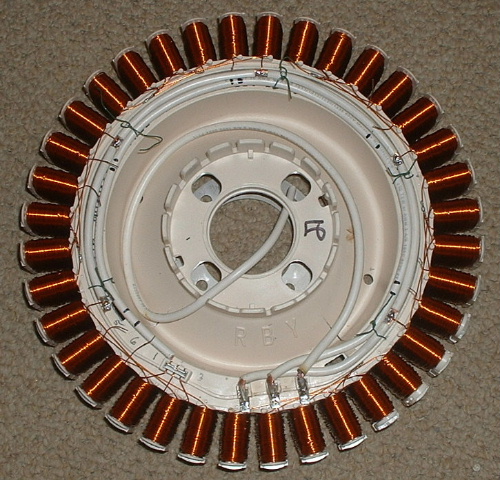
Fisher & Paykel has produced washing machine motors in three different models. A 60s, a 80s, and a 100s. They all have the same mounting dimensions. The newest model 60s has 36 coils (larger with more turns of wire). The 80s and 100s both have 42 coils, with the 80s having more turns of smaller wire and the 100 s having less turns of larger wire. All the motors are originally wired for three phase input/output and can easily be re-wired. Since the numbers 36 and 42 are both divisible by six, the following instructions can be used for all models. |
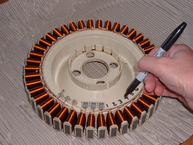 |
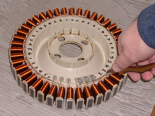
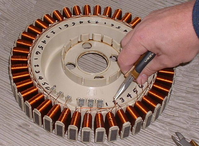
Seeing how easy these coils are to modify, I've decided on a star configuration and thought I would document my steps here to show you how really easy it is. Taking a permanent marker and starting from the coil just right of the push-on terminal strip, I've marked the coils counter-clockwise from one to six, as shown. |
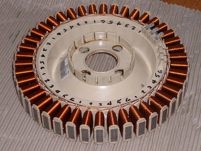 |
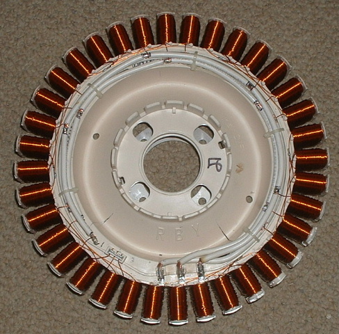
This marking method is repeated from one to six all the way around the stator. This makes the push-on terminals at the end, numbers 4, 5, and 6. |
|
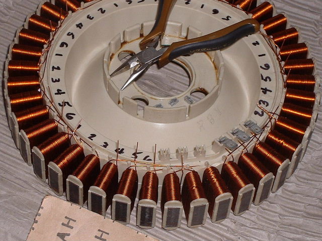
This next step is the most difficult. The rest is easy from here. With a small set of wire cutters, cut the wire that goes from coil number 1 to coil number 4, half way between the two coils. Next cut the wire that goes from coil number 2 to coil number 5. Again cutting the wire halfway between the two coils. Next cut the wire that goes from coil number 3, to coil number 6. |
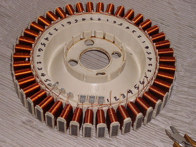 |
Here you can see where I've cut the wires and straightened them so they "stand up". By the way, you can save these pictures and view them larger on your computer. Please respect my rights and do not distribute them. |
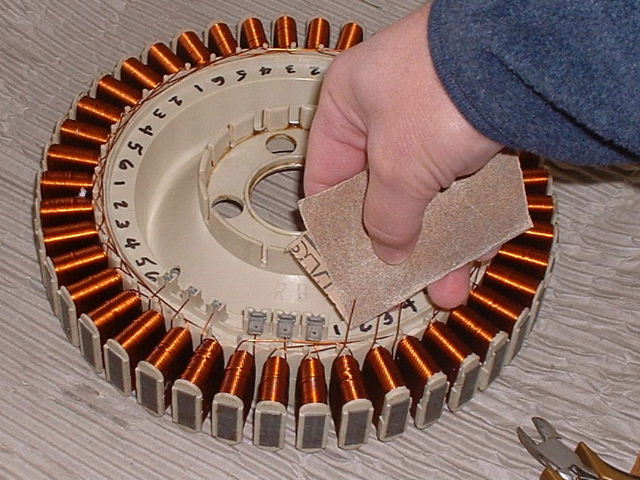 |
The wires are shellac/varnish coated and must be stripped of that coating to make good contact for soldering. There are many ways to remove this coating. One method is to use a small mini torch (which I now like)and burn the coating off, followed by a rag to wipe the ash. Another, is to use a knife to scrape the coating. I like using some plain old sandpaper. I simply wrap the wire and gently pull. A close inspection should show how well you have done. Some "ScotchBrite" or abrasive cloth should also work. This needs to be done to all the wires after you cut them. |
 |
The next step is to connect the wires from coils one, two, and three together. This pattern will be repeated all the way around the stator. Solder these three wires together and bend the connected end down out of the way. These could be insulated with a small piece of heat shrink tubing. |
 |
This also includes the last three wires that may be in small clips by themselves. Be careful, those wires are shorter than the ones that you have cut. The newer model 60s have a jumper here so you don't need to solder them together. (Note: I noticed an open area between coil number three and coil number four and drilled a small 1/8" hole in the plastic flange to provide a "tie-down" that will show up in my later pictures.) |
 |
You will need three pieces of wire about 18 inches long. Here I have used ten gage wire because it is good for about thirty amps. By wiring in this method, what I am doing is connecting two sets of coils in series and then wiring them in parallel with the rest of the coils in that phase. This first wire will be for the number 4 coils. Here I am getting ready to form the wire to fit tightly against the short flange near the coils. You need to make a "bare" spot along the wire to solder the numbered coil wire end to it. (this picture and the following look different because they are of the new 36 coil model 60s.) |
 |
To do a neat job, you need to pre-form the wires before you solder them in place. I started first soldering the wires to the push-on terminals. I've found that with this size of wire it is best to have a 100 watt or larger soldering iron to do a good job( I've found the mini butane torch works well). Here you can see that I have formed the wire and marked it for the areas that need to be bare for the next set of connections. The first wire that I am using will be connected to all the number 4 coils. |
 |
Here you can see my progress with the number "4" phase done, in process of marking the number "5" phase wire. I used a short piece of wire as a "twist-tie" to hold the wires in place. This is threaded thru a small hole in the flange near coil number three. This was done prior to the placing of the first 8 gage wire. If you missed this, I'm sure some hot melt glue would also work well. |
 |
The number "6" "push-on" terminal gets wired next. This gets connected to all the number "6" coils. You can see that the bare spots in the main wires are staggered so they won't short against each other. |
 |
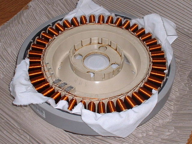
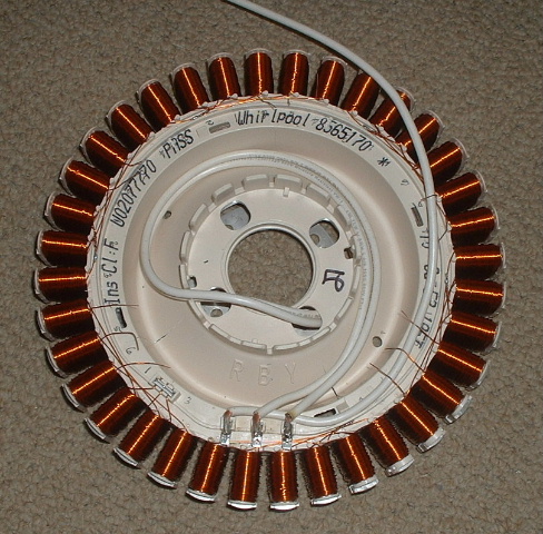
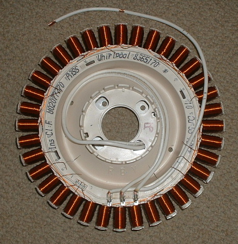
Here is my finished re-wired stator. I've replaced my temporary wire twists with some good looking plastic wire ties. A good coat or two of clear spray urethane to protect the stator is recommended. |
|
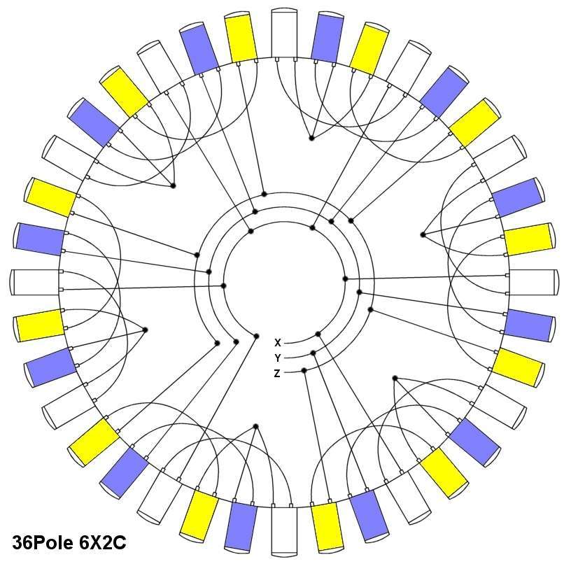
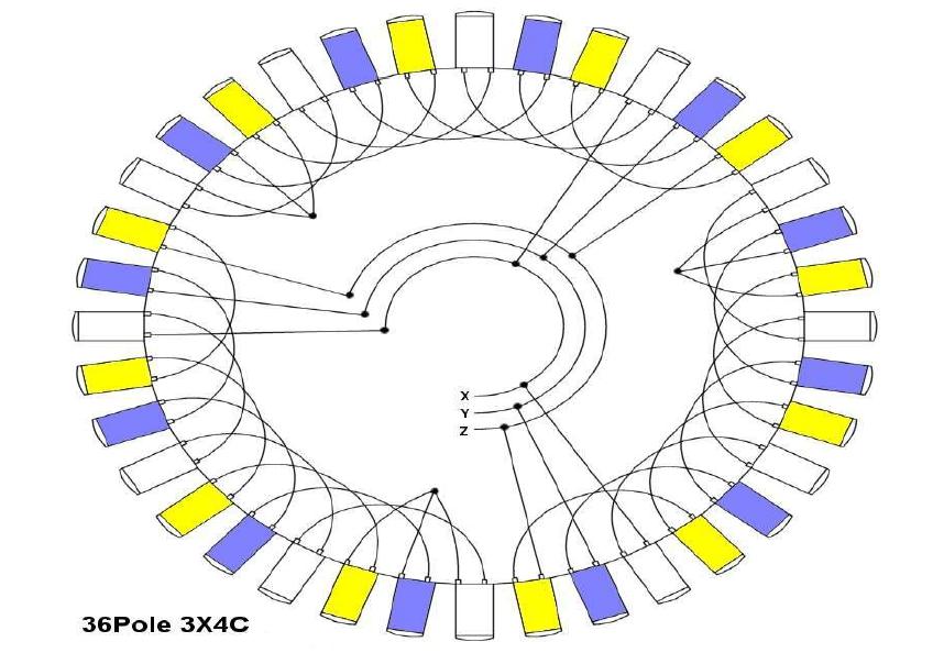
Here is a schematic that can be used for a slower turning mill like a drag style Lenz II VAWT.
|
This is the schematic for what we have just done. Six sets of two poles. This method is typically used when the mill is turning quite fast. The F&P motor as a generator puts out about 0.9 watts per RPM. This output is linear and doesn't matter how you have it wired. The main reason we re-wire these stators is to reduce the voltage, thus increasing the amperageoltage, thus increasing the amperage. |
| EcoInnovation in New Zealand | DIY Windmills in Australia |
| http://www.ecoinn.co.nz/ | http://www.thebackshed.com/windmill/ |