Wind Genny
It seems that everyone has their own idea for a simple wind generator. After searching the web, I put together this idea. This idea is not unique, but it is cheap and easy. Why am I doing this? Because I am seeing too many days of good wind and I am not ready with my Vertical Shaft Windmill.

I went to the local home improvement store and bought some pipe, a reducing "T", a pipe cap and some 3/8-16 all thread. The alternator is a GM 7127 that I happen to have laying around. My web search has found a company that provides a high voltage stator coil, another that provides "bolt on blades", and a third that has an electronic field controller to simplify my battery charging concerns.


A little paint helps a lot. The small light on top is wired to the field. No, this is NOT a PM alternator. The light will enable the field to be self exciting and indicate when the alternator is not charging, so it can be disconnected from the battery bank. (low tech)

My carbon fiber blades arrived. I painted the tips and hub white. Now I need a day with little or no wind to put this on top of my tower. A source for the 7127 Alternator is AutoZone, the stator conversion kit from MTM Scientific, the carbon fiber blades and hub from Picou Builders Supply, Co Inc.( Survival Unlimited .com) and the pipe and fittings from Home Depot. Total about $135.00 As soon as this genny gets turning and connected, I'll compute a cost per watt.


A nice day and time for more work. I've decided to mount the blades on the hub after I get it up.

After careful measurement, it is discovered that I can't reach the hub from the aerial platform with the current pole length.
16" are cut off and the pipe measured for proper diameter. For some reason the new section of pipe is fatter by .015".
With a file and some sandpaper it only takes two hours in the sun to reach the proper dimensions.
DISASTER! While hoisting the Genny up, the rope broke. It fell about 28'. I was too upset to take any pictures. It turns out that the pipe fitting method has some advantages. With two pipe wrenches I was able to straighten everything out. Some fresh paint and you can't tell the difference.

Another perfectly calm day. The first in weeks. With a helper at the rope, I was able to hoist it onto the platform. Guess what? With my poor knees and fear of heights, I can't lift the pole up and balance it enough to get it into the holder. In the mean time I have it lashed to the tower in case the winds pick up.


The picture above is three 10' pieces of 3/4" electrical conduit. Under two bucks each at the local hardware store.


Being the engineer that I am, I built a tripod hoist so that I can lift the Wind Genny and place it by myself. Who else can you count on?
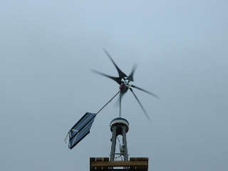
It's alive!! Now I need to connect the wires to my battery bank. But that will have to wait for another day.

I survived some high winds the other night. The gusts were hitting 35 and 40 MPH. The "Genny" made some noise but came through well. With the standard regulator in the car alternator, the "cut in" doesn't occur until about 12 MPH. Way too high for my conditions. The problem with the car alternator is that at zero rpm, it produces or draws no current, but at low RPM before it cuts in, it consumes current. Yes, it almost killed my battery. I know that I am side tracking from my vertical shaft goal, but I bought some smaller "neos" to make a PM car alternator.

I rewound a stator off an alternator that I bought online. It originally had 4 turns of 14 Ga. wire. I calculated that I could fit 10 turns of 18 Ga. wire in the slots. (I remember rewinding slot car motors with fewer turns of larger diameter wire. The motors would then draw more current and have more power. It was great on the tracks that used car batteries for a power source, but I got yelled at when I would run at the local track that used a transistorized power supply for sucking too much current. Boy, that was a few years ago!) I miscounted and made my coils with 11 turns instead of ten. It turned out OK for the first layer (phase) but it was a real bear trying to get those 4 extra wires into the last layer.
I tried to "press" off the old rotor with no success. Instead, I milled a pocket into each finger for the "neo" magnet.
I hate to admit it, but I failed with the hand wound stator. Several of the coils were making contact with the metal laminations and causing a short. What's next? I bought a 38 Volt DC Ametek tape drive motor. When I received it, I rotated the shaft by hand and expected to feel the magnets cog. Nothing. I marked the end caps and took it apart. What a beautiful high quality motor. The rotor was skewed so it would have a good starting torque. I connected the volt meter and was able to get 9+ volts turning the shaft by hand. Next, I shorted the leads and found the shaft almost impossible to turn. This motor definitely has potential.
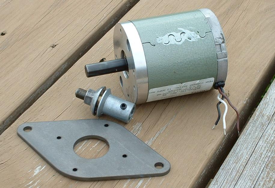

I made an adaptor plate so I could bolt the motor/generator to the same mounts that I used for the car alternator. A trip to the hardware store for the shaft adaptor and a coat of paint makes it ready to mount.
Its not quite as large as the car alternator, but the slightest breeze starts it spinning. I wish I would have gone this route to begin with, but I guess that's how you learn. A blocking diode keeps the generator from turning into a motor. It takes about a 7-8 MPH wind to generate the 13+ volts needed to overcome the battery resistance and start charging. This looks like it will be a successful wind charger. I just may have to make up kits or plans for this.

Here is a shot of my old "Battery Bank". As you can see it is quite limited. I am working on a new board that will be installed in the blank spot above the battery. It consists of a battery charge indicator, resistor load, cooling fan, bridge rectifier, charge controller, and terminal strip with fuses. I love my "Ametek" generator. The other day with a nice 10 MPH breeze, fully charged battery, the charge controller closed the relay to my dump load. I put a meter on it and read 16 plus volts at 3 amps with an 8 ohm load. (4 two ohm 100 watt resistors wired in series.) Not too shabby.

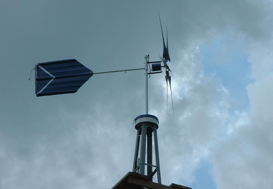
Here is a picture of my furling mechanism that I am working on. The Ametek generator mounts off to the right, and the tail mounts on the angled pipe to the rear. When the wind blows hard, the "Genny" rotates back out of the wind, lifting and twisting the tail. As soon as another calm day arrives, I'll try to get this mounted. I don't like hearing the blades touch the pole at 40 plus MPH. It sounds like a helicopter is trying to land on my house. Many people have asked about my Ametek " kit". The answer is, that I am working on one.

Yep. I'm at it again. You can see I've added an Amp and a Volt meter to my panel. This way I can get some good power readings. You can also see that I've picked up a massive Tape drive motor, and as long as I've got my "Genny" down to put on my furling mechanism, I'm going to "swap it out". I believe that I can realistically get three times my current output. (close to 700 watts?)

Tape Drive motor attached to furling mechanism. How do you like those fancy brackets? It won't go up till I rebuild the "motor". I opened it up and decided that the bearings need to be replaced. Of course it will need a coat of paint to protect it from the elements.

Up and running.


Its hard to read the meters in this picture but at about 13 mph I'm dumping 10 amps at 20 volts into my shunt load = 200 watts. Yes, I'm happy.
I just love wind generators.
Updated pictures will be posted as I progress.
 |
|
|