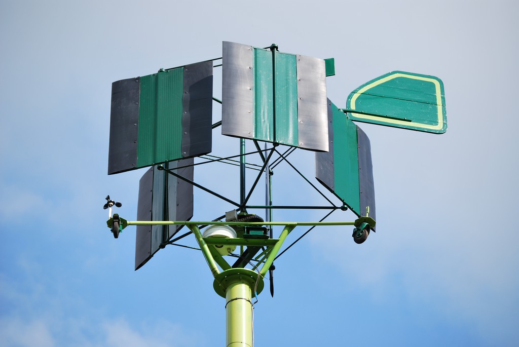
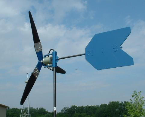
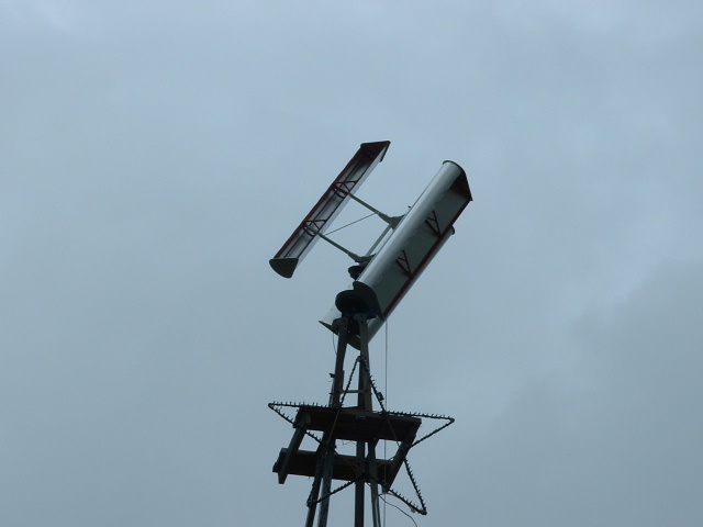
Years ago when I was working on a project for a truf aerator, I had an idea for a unique moving vane windmill. (1979). The above picture is of a similar one made by Luc Haegman. When I first saw his video I cried. It was so beautiful. The following will take a while to load since there are a lot of images. The latest updates are at the bottom, if you've read this page before.
Luc Haegeman of Belgium has made my dream a reality!
Here is the link to his YouTube video. Check it out!
https://www.youtube.com/watch?v=pGs_JTVK2NI
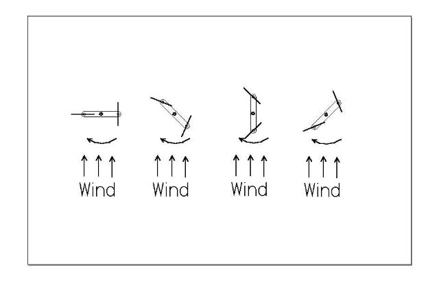
The above schematic represents the principle behind my vertical shaft windmill. I had to explain this to several people, so I thought I had better post something a little easier to understand. The vanes are turning half the speed of the main shaft. I estimate the speed of my windmill to be in the range of 70 to 200 rpm.
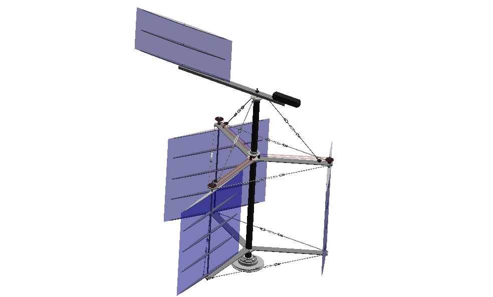
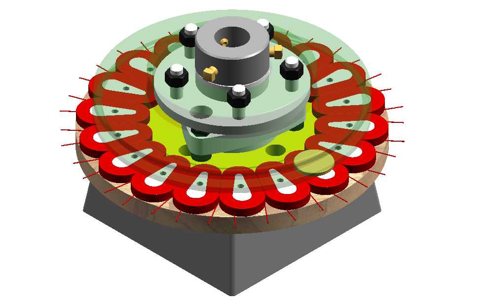
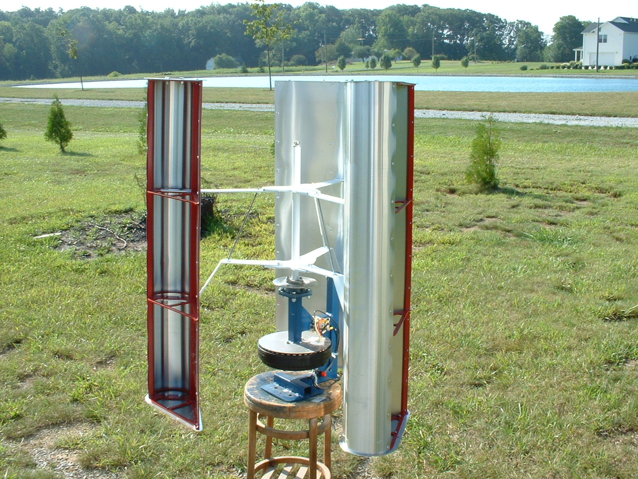
The above image is a solid model of my cyclometric vertical shaft windmill design. I got the basis for this idea from an article in a 1978 Design News magazine. They showed a large vertical shaft windmill utilizing two vanes or blades. Mine has three. The vanes rotate as they spin around the center shaft. There is a 1:2 reduction via a chain and sprocket. This enables the vane to be perpendicular to the wind on one side of the shaft, and parallel when it comes around to the other side. I am currently in the process of building this windmill. The vanes are 3' square, turning a 1 1/2" pipe mounted on a auto wheel bearing assembly, with a 10" disc brake rotor. The rotor was going to be edge machined to accept a standard 4L "V" belt to drive a standard automobile generator. However, after researching the GM alternator, I've changed my mind, I am going to build my own low speed home built alternator, based on a wooden PM alternator I saw on the Otherpower webpage. Check out www.otherpower.com. If you are interested in this project, please e-mail me at the below address.
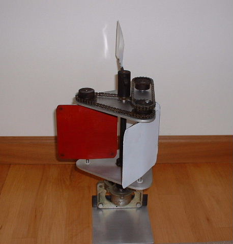
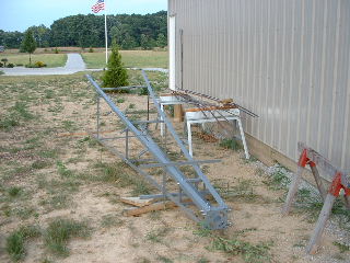
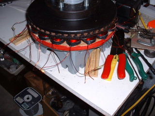
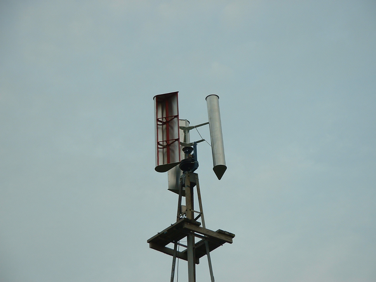
Above is a picture of the prototype that I built in 1987 to prove the concept. It sometimes takes me a while to get things done, but I never stop thinking about them.
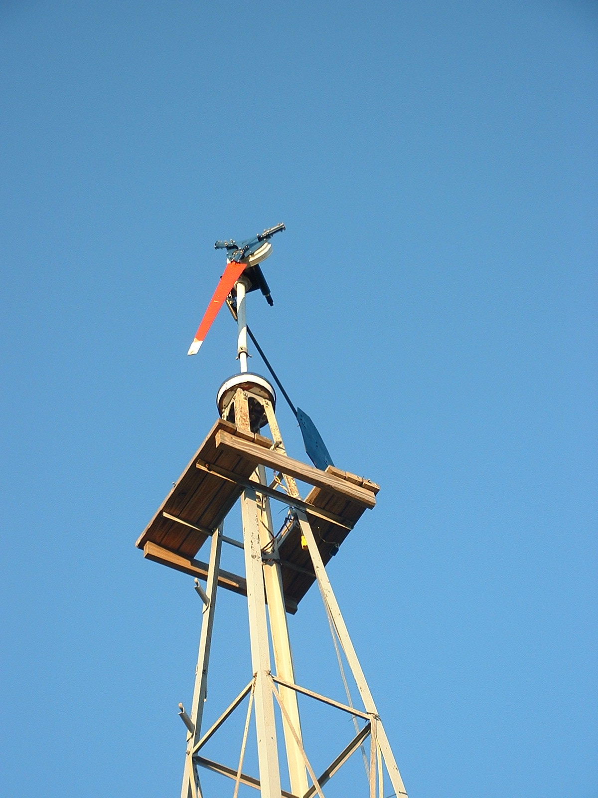
Twenty plus years ago I found this antique windmill tower for sale. I thought it would be perfect for my project.
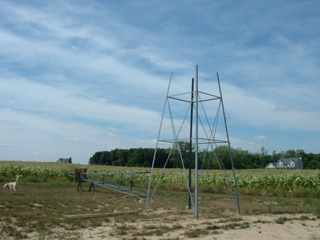
When I bought it, it had been used as a windsock at a small airfield. That airfield was one of the oldest in the country, Korn Field in Montra, Ohio. The Korn brothers were contemporaries with the Wright brothers, so this tower is probably over 100 years old. Those trees in the background are over 700' away, so there is nothing blocking the wind.
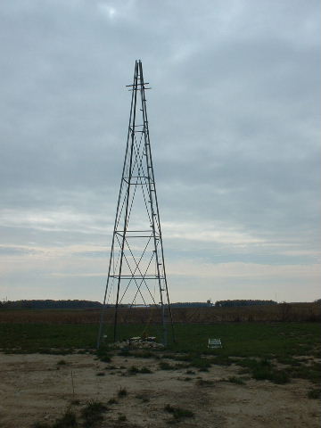
The erected tower stands over 33' high.
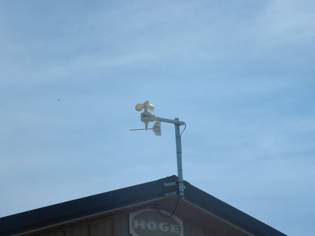
I purchased a wind speed indicator to get some baseline data while I was building the windmill. There is a link for this on my links page.
Here is the original concept image of my alternator design. I thought I had a good idea. I was wrong.
Here is a shot of the items I bought for the mechanics of the windmill.
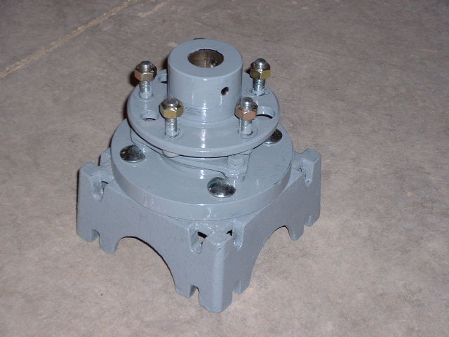
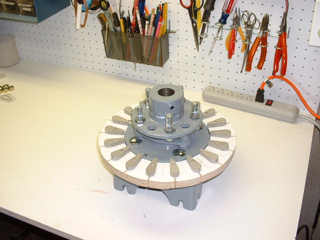
Here is the automobile hub mounted to an adaptor plate, which is mounted to the tower casting. The collar above the hub, gets pressed in to give additional load area for the center pipe.
Here is the hub with the 10" disc brake rotor.
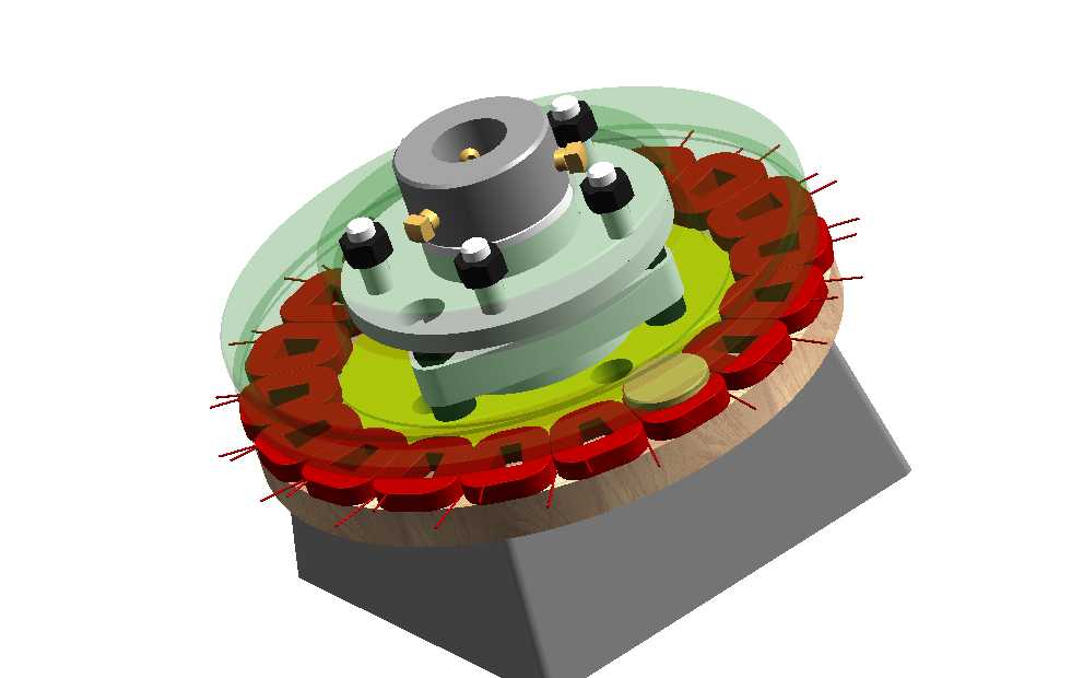
I realized that the round coil design did not utilize the maximum magnet area, so this is a revision.
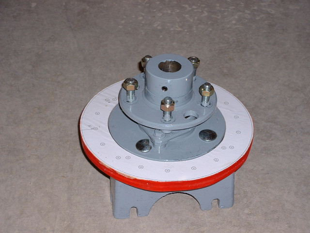
A little paint sure makes things look a lot better.
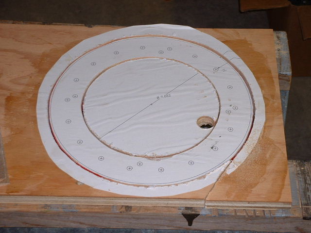
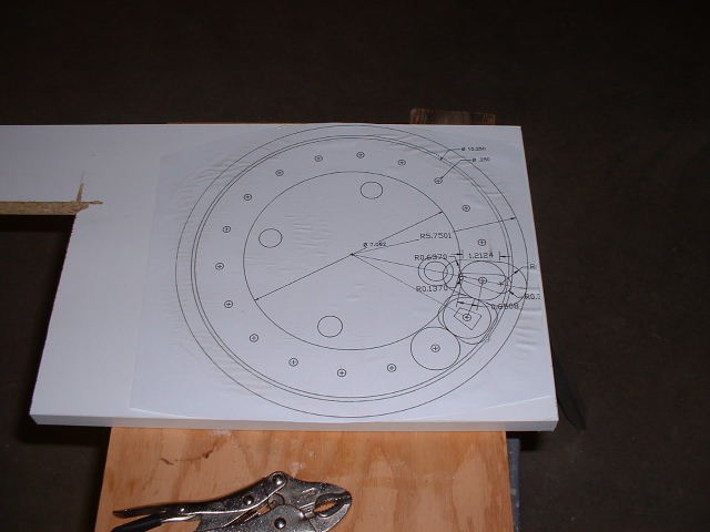
A paper pattern glued to the plywood for coil spacing and mounting.
Good dimensions make for a good fit.
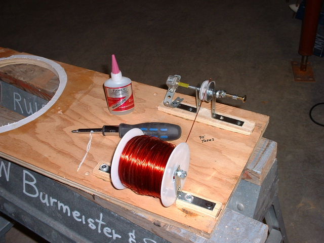
Winding coils by hand is not easy. A counter connected to the crankshaft helps.
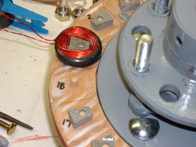
The first coil in place. Notice that the coil doesn't match the pencil outline. There is a difference between as designed and as built.
The center coil form allows for a uniform coil height when glueing.
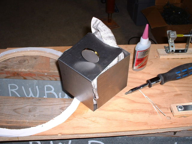
The "neo" magnets arrived via UPS in a metal box. I wondered what would keep them from sticking to the side of the truck.
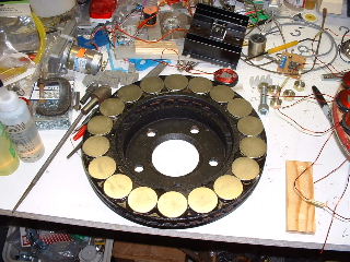
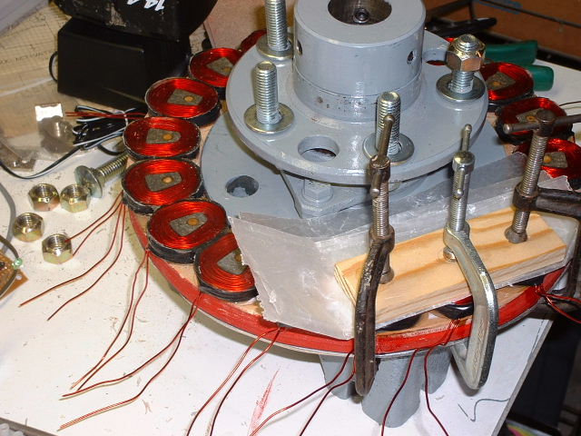
The 18 neo magnets glued into place. Please don't look at the messy bench. I'm an inventor.
It's hard to see, but that glow at the very edge of the bench is a small lamp connected to nine of the coils in series. I'm spinning the rotor while taking the picture.
After consulting other experts in the field, it was determined that my coil was the wrong size for my magnet. The magnetic field should pass through the straight side of the coil. Passing over the curved area reduces the induced current. The above image shows the revised coil.
Here is the new cutting pattern. You can see the difference in coil size.
The revised coil forms in position. Please note that I did clean up my bench.
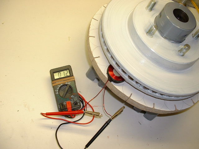
I am cranking the rotor and taking the picture at the same time. Not an easy task. The recorded voltage was a little higher.
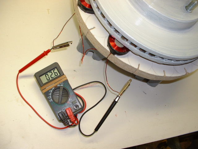
Success! Two coils connected in series. Note that I skipped a space so they would be "in phase".
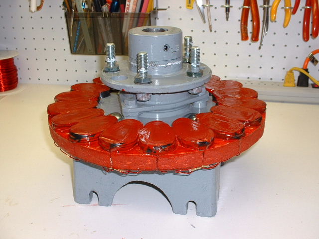
Here I've also put on a coat of enamel paint to help protect the epoxy.
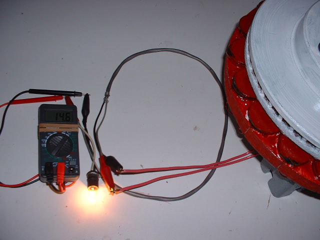
Success! It's hard to see, but the meter is reading 14.6 volts with me cranking by hand. Now it's all up to my mechanical portion of the windmill design to prove it also can be successful. But that didn't happen. I got side tracked on other projects and windmills.
I've had some successes and some failures along the way.
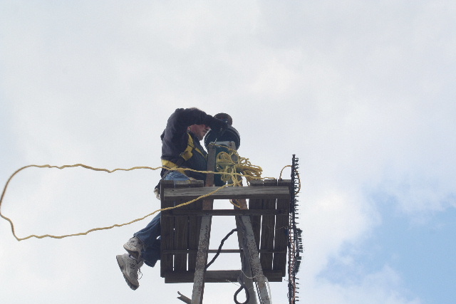
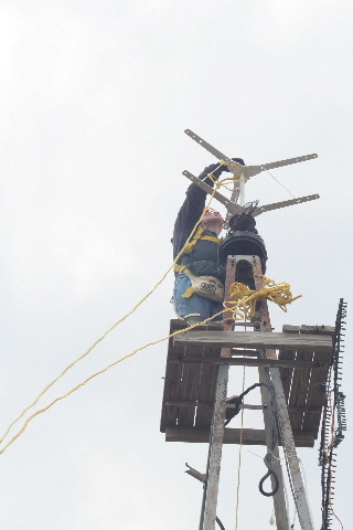
More than one person thinks that I am crazy to climb up my tower and work on my windmills. Especially the Doctor that replaced my hip and knee. He just can't understand what drives me to do these things. Can you?
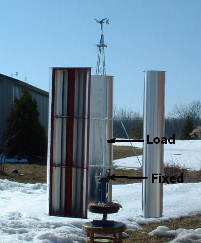
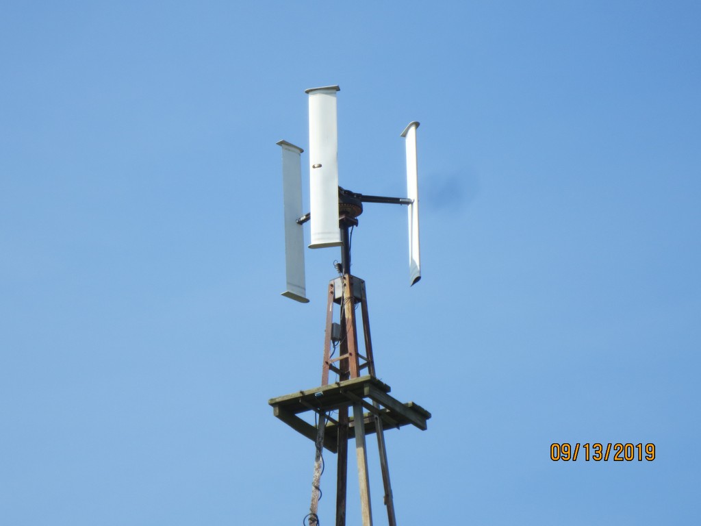
The bending moment for the wind loading was just about at the center of the shaft, about 14 inches away from the bearing support. Not Good! My "new" VWAT design did not last even one day, of course it was a very windy one.
It's hard to tell from these pictures but I dropped the bending moment almost 9 inches, placing it just above the upper bearing support. This should prove to be a very strong and reliable windmill, of course now I just need some wind.
 |
|
|